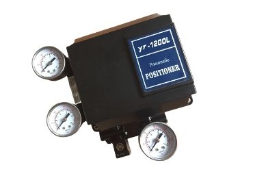
YT-1200L Electro-pneumatic Positioner
The Pneumatic positioner YT-1200L is used for pneumatic linear valve actuators using pneumatic controller or control systems with an output signal of 3 to 5psi or split rages.
- Price Term: FOB/CIF/EXW/DAP
- Package: Exported Wooden case or according to customer request
- Delivery Time: 7 to 10 working days
- Transports: By sea, by air, by high express
- Shipment Port: Shanghai Port
- Origin of Place: Jiangsu
- Warranty: 12 Months
- The size is compact.
- The change of RA/DA Action is convenient,it can apply to the single or double-acting actuator.
- It is possible to prevent hunting with the orifice to the small-sized actuator.
- It is economical due to less air consumption.
- It can control the 1/2 split range with simple operation without the replacement of parts.
- Working Principle
- Features
- Specification
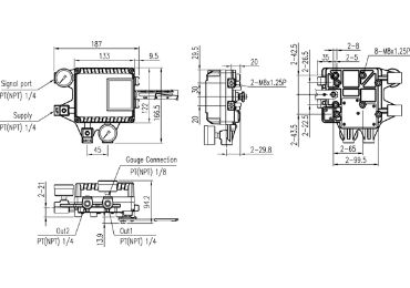
- Dimension
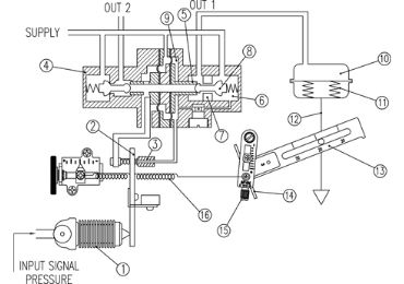
When INPUT SIGNAL PRESSURE increases to open the valve, ① the bellows stretches and pushes ② the flapper to the opposite side of ③ the nozzle. The gap between ③ the nozzle and ② the flapper becomes wider and from the inner part of ④ the pilot, air inside ⑨ the chamber is exhausted through ③ the nozzle. Due to this effect ⑤ the spool moves to the right. Then, ⑦ the seat blocked by ⑧ the poppet pushes the poppet away and supplied pressure (air) goes through ⑦ the seat and OUT1 Port and enters into ⑩ the chamber of the actuator chamber. Then ⑩ chamber’s pressure will increase, and when there is enough pressure inside the chamber to push ⑪ the actuator’s spring, ⑫ actuator’s stem will start to go down. Through the feedback lever, the stem’s linear motion will be converted to ⑭ span lever’s rotary motion. This ⑭ span lever’s rotary motion will rotate ⑮ the span and pull the spring once again. When the valve’s position reaches the given input signal pressure, ⑯ span spring’s pulling force and force of ① bellows will be balanced and move
② the flapper back to its original position to reduce the gap between ③ the nozzle. The amount of air exhausted through ③ the nozzle will reduce, and ⑨ the chamber pressure will increase again. ⑤ Spool will move back to its original position on the left, and⑧ the poppet will also move in the same direction blocking ⑦ the seat to stop the air coming into the ⑩ chamber through the SUPPLY. As a result, the actuator will stop operating, and the positioner will return to its normal condition.
- The size is compact.
- The change of RA/DA Action is convenient,it can apply to the single or double-acting actuator.
- It is possible to prevent hunting with the orifice to the small-sized actuator.
- It is economical due to less air consumption.
- It can control the 1/2 split range with simple operation without the replacement of parts.
| Item.Type | Single | Double |
| Input Signal | 0.2~1kgf/c<rf(3~15psi) | |
| Supply Pressure | 1.4~7kgf/arf (20~100psi) | |
| Stroke | 10~ 150mm | |
| Air Connection | PT(NPT)1/4 | |
| Gauge Connection | PT(NPT)1/8 | |
| Protection | IP66 | |
| Ambient Temp | -20-70°C (-4~158°F) | |
| Linearity | ±1%F.S. | ±2% F.S. |
| Hysteresis | ±1%F.S. | |
| Sensitivity | ±0.2% F.S. | ±0.5% F.S. |
| Repeatability | ±0.5% F.S. | |
| Air Consumption | 3LPM (Sup=1.4kgf/㎝², 20psi) | |
| Flow Capacity | 80LPM (Sup=1.4kgf/㎝², 20psi) | |
| Material | Aluminum Diecasting | |
| Weight | 1.7kg(3.1lb) | |

Installation of YT-1200 series
The Pneumatic positioner YT-1200L is used for pneumatic linear valve actuators using pneumatic controller or control systems with an output signal of 3 to 5psi or split rages.
1.1 Safety
When installing a positioner, please ensure to read and follow safety instructions.
- Any input or supply pressures to the valve, actuator, and other related devices must be turned off.
- Use bypass valve or other supportive equipment to avoid the entire system “shut down.” q
- Ensure there is no remaining pressure in the actuator.
- The positioner has a vent cover to exhaust internal air and drain internal condensation water. When installing the positioner, make sure the vent cover must be facing downward. Otherwise, the condensation water could cause corrosions and damages to internal parts.
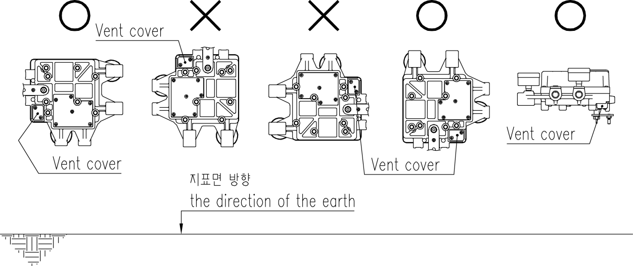 Fig. 4-1: The correct positions of a vent cover
1.2 Tools for installation
-
- Hex key set for hex socket cap bolts
- (+) & (-) Screwdrivers
- Spanners for hexagonal-head bolts
1.3 Linear positioner Installation
Linear positioner should be installed on linear motion valves such as globe or gate type
which uses spring return type diaphragm or piston actuators.
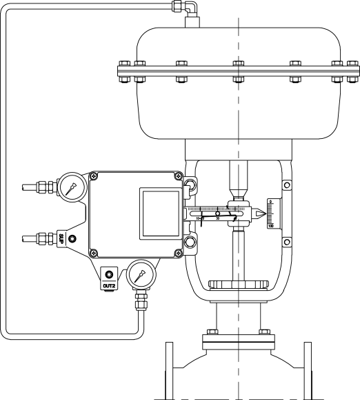
Fig. 4-2: Installation example
Before proceeding with the installation, ensure the following components are available.
- Positioner
- Feedback lever and lever spring
- M6 nut and spring washer (fastening feedback lever to the main shaft)
- Bracket, bolts, and washers for positioner – not supplied with the positioner
- Connection bar – not supplied with the positioner
1.4 Preparing Bracket for the positioner
A proper bracket must be made to adapt the positioner on the actuator yoke. Please consider the following important points when a bracket is being designed.
-
- The positioner’s feedback lever must be vertical to the valve stem at 50% of the valve stroke.
- The connection bar of the actuator clamp for the feedback lever should be installed in such a way that the valve stroke length coincides with the corresponding figure in “mm” marked on the feedback lever. The improper setting may cause poor linearity
1.5 Installation Steps
1. Assemble the positioner with the bracket made in the previous step by fastening the bolts (M8 * 1.25P).
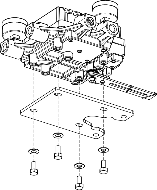
Fig. 4-3: Attaching positioner to bracket
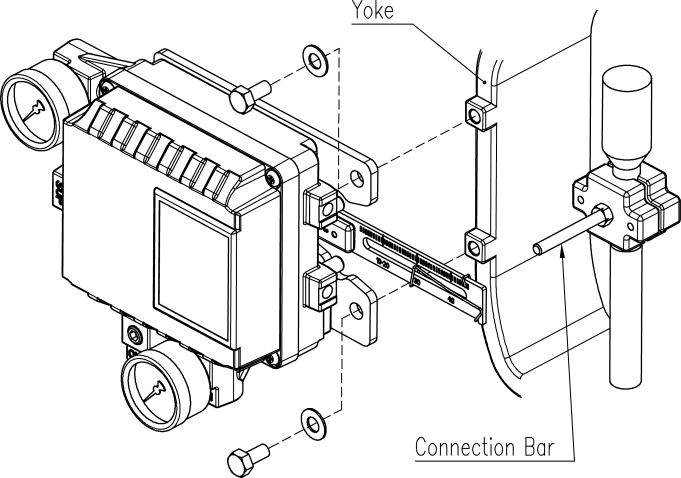
Fig. 4-4: Attaching the bracket to actuator yoke
2. Attach the positioner with the bracket to the actuator yoke
– DO NOT TIGHTEN THE BRACKET COMPLETELY.
3. Connect the connection bar to the actuator clamp. The hole gap on the feedback lever is 6.5mm so the connection bar’s outer diameter should be less than 6mm.
4. Connect an air-filter regulator to the actuator temporarily. Supply enough air pressure to the actuator to position the valve stroke at 50% of the total stroke.
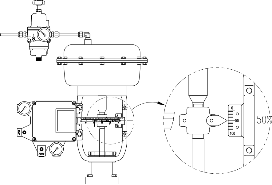
Fig. 4-5: Positioning the valve at 50% of the total stroke
- Insert the connection bar between the feedback lever and lever spring. The connection bar must be located upward from the lever spring as shown in the below-left figure. If it is located downward from the lever spring as shown in the below right figure, the connection bar or the lever spring will be worn out quickly because of excessive strong tension.
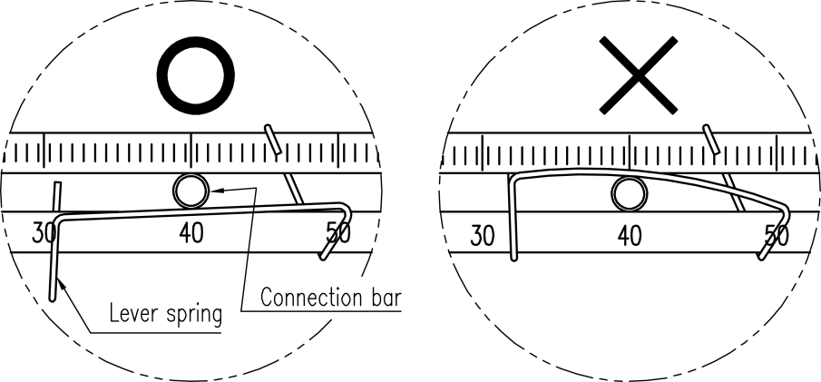
Fig. 4-6: Proper way to insert connection bar between feedback lever and lever spring
6. Check if the feedback lever is vertical to the valve stem at 50% of the valve stroke. If it is not vertical, adjust the bracket or the connection bar to make it vertical. Improper installation may cause poor linearity.
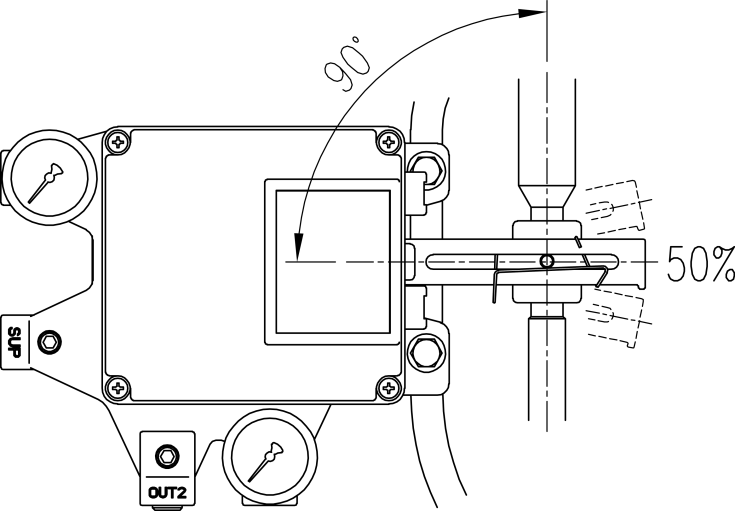
Fig. 4-7: Feedback lever and valve stem
7. Check the valve stroke. The stroke numbers are engraved on the feedback lever of the positioner. Position the connection bar at the number on the feedback lever which corresponds with the desired valve stroke. To adjust, move the bracket, the connection bar, or both.
※ The effective linear lever angle is 23 degree
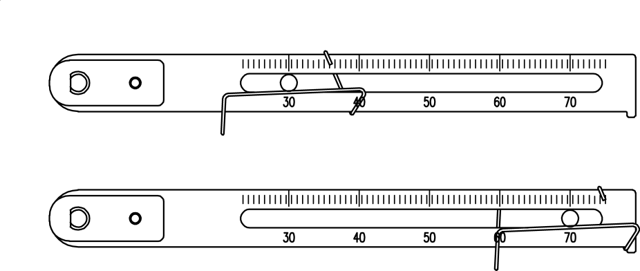
Fig. 4-8: Feedback lever and location of the connection bar
8. After installing the positioner, operate the valve from 0% to 100% stroke by using direct air to the actuator. On both 0% and 100%, the linear lever stopper should not touch the stopping bosses of the positioner, which is located on the backside of the positioner. If the linear lever stopper touches the stopping bosses, the positioner should be installed further away from the yoke.
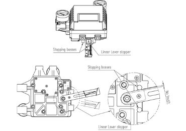
Fig. 4-9: Linear lever stopper should not touch stopping bosses of positioner on 0% ~ 100% valve stroke.
9. After the installation, tighten all of the bolts or nuts on the bracket and the connection bar.
2-1 Rotary positioner Installation
Rotary positioner should be installed on rotary motion valves such as ball or butterfly type which uses rack and pinion, scotch yoke or other types of actuators which its stem rotates 90 degrees. Before proceeding with the installation, ensure the following components are available.
2-1-1 Components
- Positioner
- Fork lever (Only Fork lever type)
- Rotary bracket set (3 pieces)
- 4 pcs x hexagonal headed bolts (M8 x 1.25P)
- 4 pcs x M8 plate washers
- 4 pcs x wrench headed bolts (M6 x 1P x 15L)
- 4 pcs x M6 nuts
- 4 pcs x M6 spring washers
- Bolts and washers to attach the bracket to actuator – not supplied with the positioner
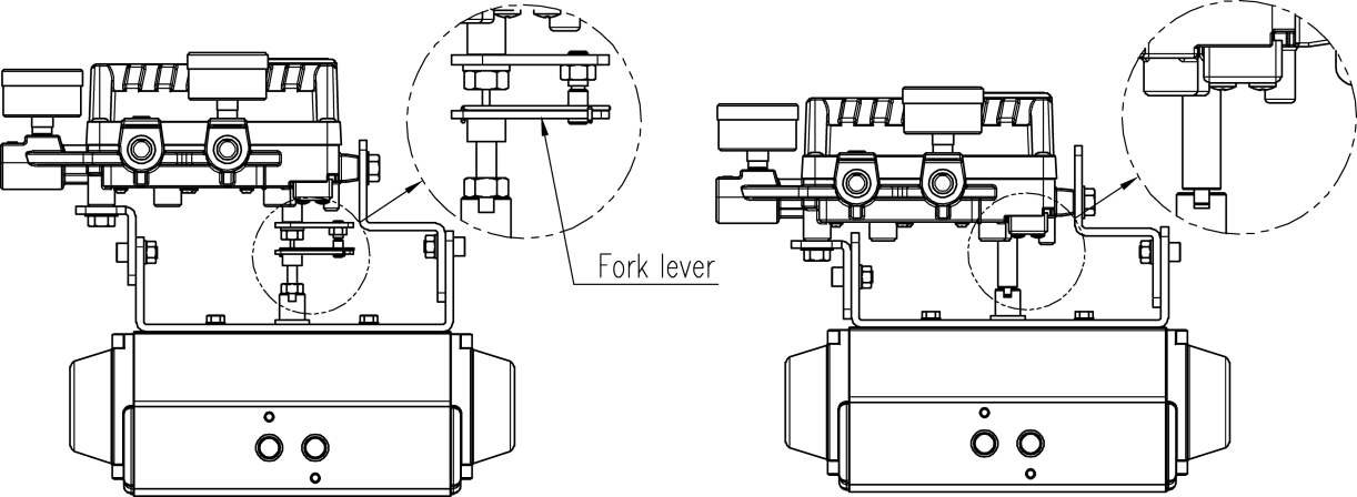
Fig. 4-10: Fork lever-type Fig. 4-11: Namur type
2-1-2 Rotary BracketInformation
The rotary bracket set(included with the positioner) contains two components. The bracket is designed to fit onto the actuator with 20mm, 30mm, and 50mm stem height (H) according to VDI/VDE 3845 standard. Please refer to the below figures on how to adjust the height of the bracket.
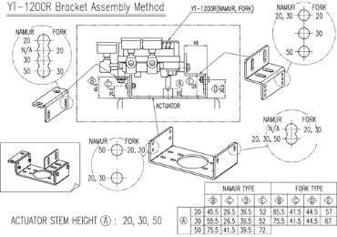
Fig. 4-12: Brackets and positioner
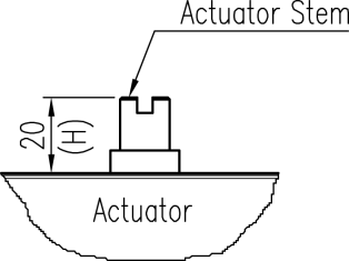
Fig. 4-13: Actuator stem Height
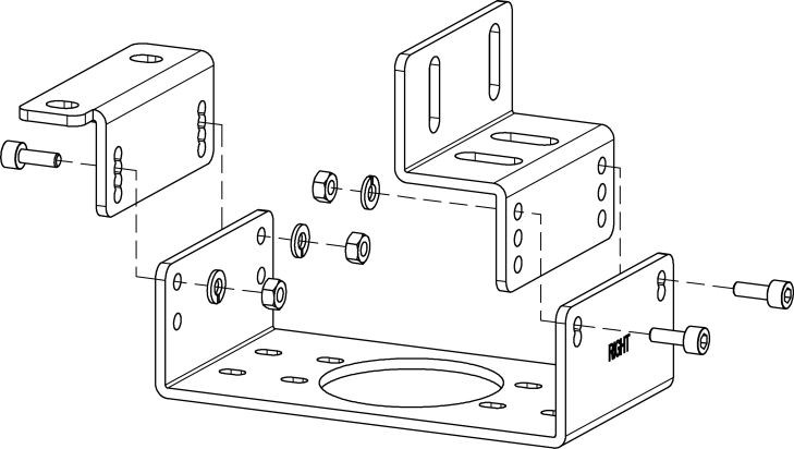
Fig. 4-14: Rotary Brackets Assembly
2-1-3 Rotary positioner InstallationSteps
1. Please check the actuator’s stem height and adjust the brackets by referring to the above bracket figures.
2. Attached are the brackets onto the actuator. It is recommended to use a spring washer so the bolts will not be loosened from
3. Set the rotation position of the actuator stem at 0%. For a single-acting actuator, it is easy to check the 0% point by supplying no pressure to the actuator. For double-acting actuator, check actuator stem’s rotation direction – clockwise or counter-clockwise – by supplying pressure to the
4. (Only Fork lever type) Install the fork lever after setting the actuator’s stem at 0%. Check the actuator stem’s rotation direction – clockwise or counter-clockwise. The installation angle of the fork lever should be 45 to the longitudinal
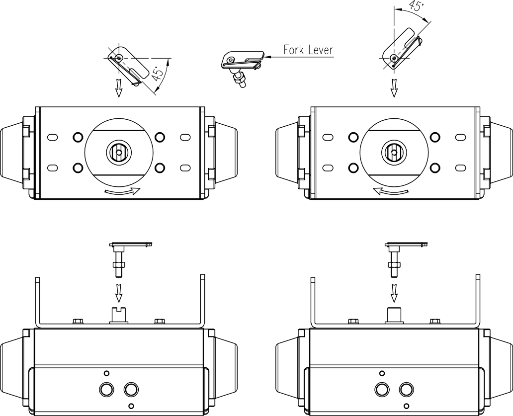
Fig. 4-15: Counter-clockwise and clockwise rotation.
5. (Only Fork lever type) After determining fork lever direction, adjust F between the top plate of the fork lever and the top face of the actuator as below table. Fasten lock nuts which are located on the bottom of the fork lever.
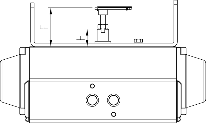
Fig. 4-16: Height of fork lever
| H | F (only No. 1 & 3 fork lever) |
| 20 | About 44 |
| 30 | About 54 |
| 50 | About 74 |
6. Attach the positioner to the bracket. <Only fork lever type: Fix the clamping pin (5mm Dia.) into the fork lever slot and insert the center pin (2mm Dia.) of the main shaft of the positioner into the hole of the center of the fork lever. The clamping pin will be locked to the fork lever spring.> Setting alignment of the center of the main shaft of the positioner and center of the actuator’s stem is very important. Poor alignment of the main shaft and the actuator’s stem decreases the positioner’s durability due to unnecessary forces on the main shaft.
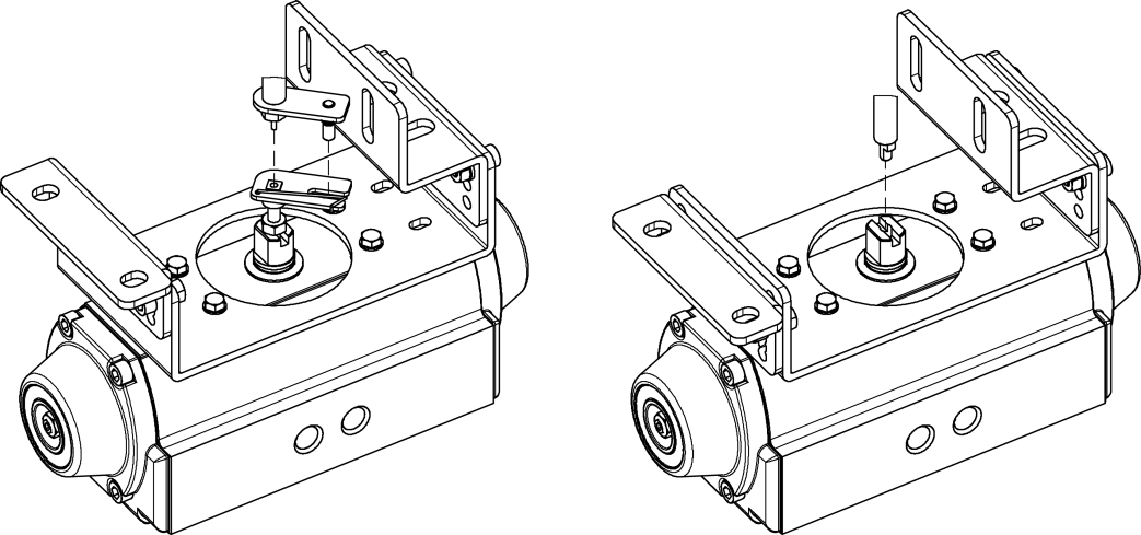
Fig. 4-17: Main shaft center alignment (Fork lever)
Fig. 4-18: Main shaft center alignment (Namur)
7. Tighten the positioner and the bracket with bolts after checking the positioner’s position