- Simple in construction.
- Easy to operate. Versatile.
- Fast and quick response.
- Operator or human involvement is not necessary.
- High accuracy.
- More compact design.
InstruthinkYour One- Stop Pressure Indicator Supplier in UK
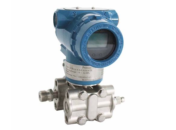
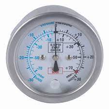
The Instruthinkpressure indicator is a tool for measuring and recording pressure variations in pneumatic devices and piston engine cylinders. It includes a pressure gauge and pressure transmitter. Pressure gauges usually have a sensing element (sensor) and transmitting and recording devices. It is a practical device designed explicitly for collective protection applications where reliable pressure measurements are needed.
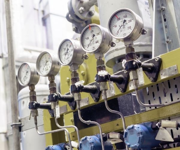
Pressure indicators are an easy way to test the performance of pumps, air controls, or regulators. Other applications the gauges are ideal for include leak testing, quick calibration of gauges and transducers, monitoring pressure drop across filters, or as a temporary replacement for pressure gauges. In addition, the pressure indicator is designed for use in ships, buildings, and other applications where reliable air pressure measurements are required.
Your Expert for Pressure Indicator Solution from UK
Best Pressure indicators Solution for Your Project
Pressure indicators are a common component in the operations of various industries, but not all indicators are created equal or suitable for every situation. Instruthinkhas been at the forefront of innovation and quality for pressure indicators and pressure instruments. InstruthinkGroup, founded in 2000, specializes in the research, development, and production of valve automation and process instruments. The range of our products includes low-cost cast models for easy installation to high-end units capable of withstanding both high temperatures and high pressures. Instruthinkcan provide you with the tools you need to revolutionize your business processes and get more done.
Contact us and let’s work together. Reach out to one of our experienced engineering teams today, and we’ll find custom-tailored solutions that meet your needs. Feel free to let us know about any special requirements your business has and we’ll work on coming up with custom solutions for you.

PRESSURE INDICATOR – A COMPREHENSIVE GUIDE
What is the purpose of an electronic pressure indicator?
An electronic pressure indicator transmitter can measure both gauge and absolute pressure. Differential pressure measurement is made using the 2-channel version of the CPH6300-S2 with two reference pressure transmitters connected. You can measure in the following units: bar, mbar, psi, Pa, kPa, MPa, mmHg, inch, and mH2O.
An electronic pressure indicator transmitter can be successfully used in a wide range of applications thanks to the built-in data logger and other functions such as Minimum, Maximum, Hold, Taring, zero-point adjustment, alarms, power off, peak detection (up to 1000 measurements/s), averaging filter, etc. The CPH6300 digital pressure transmitter has a large backlit display and a long battery life.
In addition to the soft datalogger software for tabular and graphical presentation of recorded data, there is the WIKA-Cal calibration software for performing the calibration procedure—instrument in the SQL database.
What is the installation method of an electronic pressure indicator?
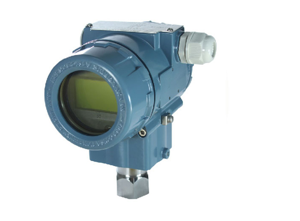
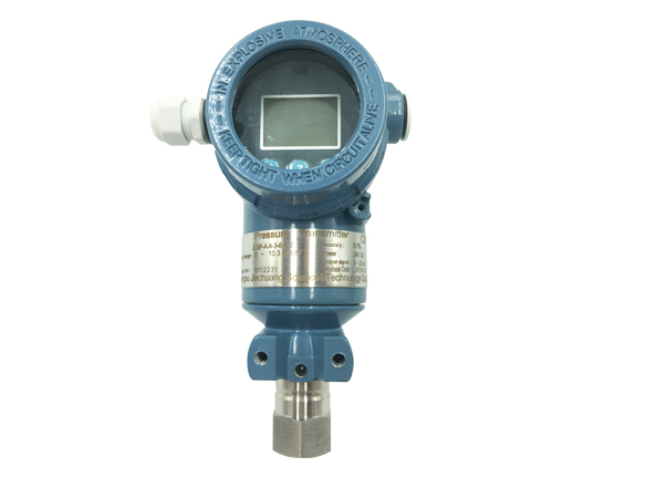
The display is installed directly on the sensor and does not require additional power. The setting is made using the buttons on the front panel. The case and display of the indicator can be rotated about their axes. After installing the sensor, you can adjust the spatial position of the display so that it is convenient to read the readings. The LED board allows using the indicator at negative temperatures.
What should be considered when choosing a digital pressure indicator?
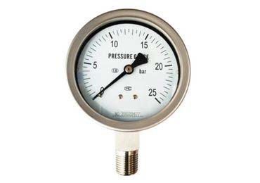
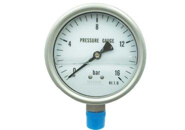
Choosing a digital pressure gauge can be tedious if you don’t know the differences between all types of pressure gauges. A digital manometer is any pressure measuring device that digitally indicates pressure using an electronic display. A digital pressure gauge is presented instead of a dial pressure gauge which uses a purely mechanical component to sense and indicate pressure.
Dial pressure gauges have been used in the industry for a long time. They usually indicate pressure using a manometric tube, which is mechanically connected to a dial and rotates on a graduated circular scale. They are designed to give a local visual indication of the pressure in a process but generally cannot transmit the reading.
A digital dial gauge is a good choice for directly monitoring a continuous process at a single point. A pipeline, tank, or other pressurized vessel containing liquid or gas may require an accurate, high-resolution local pressure indication.
A digital dial pressure gauge can be connected directly to the process at the location of interest. Large backlit digital displays minimize reading errors. Digital dial gauges can also provide wireless or electronic communication for remote monitoring or data collection.
What are the functions of the mechatronic pressure indicator?
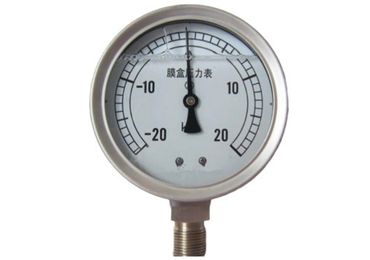
The mechatronic pressure indicator works on the principle of a spring-loaded piston. This piston, located in the seat of the valve body, is lifted by the fluid flow, meeting the resistance of the spring. The position of the piston determines the flow.
When the flow decreases, the spring acts on the valve and returns it to its original position, preventing backflow. Due to the robust mechanical design, the sensor can be used at high pressure and in harsh environments.
The mechatronic pressure indicator range includes flow sensors with analog output and flow sensors with switching output. The switching points of the sensors can be set and fixed with an adjusting screw. Different types of threaded connections are offered depending on the detected volume flow.
What is the purpose of a mechanical pressure indicator?
A mechanical pressure indicator is a self-recording pressure gauge used to record indicator diagrams of fast-flowing systematic processes of pressure changes in the cylinders of reciprocating machines.
The sensitivity of the mechanical indicator, which depends mainly on the elastic properties of the spring and the gear ratio of the writing mechanism, is very constant.
Mechanical indicators are calibrated on a particular device by loading the piston with a certain weight. At each loading, the deviation of the writing mechanism is noted by drawing lines on indicator paper.
Instead of a mechanical indicator in smaller dimensions, an electrical sensor can be placed. Since the springs of vibrometers must be very soft, with a vertical arrangement of the vibrometer, the seismic mass receives a significant static settlement under the action of its weight.
Which is taken into account in the design of the vibrometer. Therefore, sensors of vibrometers and vibrographs are used to measure horizontal and vertical displacements, which differ in the suspension of the seismic mass.
The operation of mechanical indicators is based on balancing the pressure arising in the pump cylinder and acting on the device’s piston by the force of elastic deformation of the rod spring. The mechanical pressure indicator consists of four main parts: a frame, an indicator head, a writing mechanism, and a drum that serves to attach the indicator paper.
What are the advantages of mechanical pressure indicators?
This device has a lot of advantages; otherwise, it would not be so popular among motorists and mechanics. In particular, among the advantages of a mechanical pressure gauge, the following should be mentioned:
- Such a device is effortless to buy and use, and you do not need to receive special education or technical training.
- Everyone can buy a mechanical pressure gauge, regardless of their wealth.
- Ease of use. To get the result, you have to make a minimum of effort.
- Even though modern electronic pressure sensors bypass the mechanical pressure gauge in the accuracy of the results obtained, it remains a reasonably accurate device.
- Availability of additional buttons. For example, the device can be equipped with a button to release air or knock down the result. All this makes it even more practical.
What is the purpose of diaphragm seals?
Diaphragm seals are sharpened and rubbed with graphite before assembling, after which they are installed in the grooves of the diaphragms. Locking screws and washers for seals and diaphragms are rubbed with graphite mixed with mercury ointment. The position of the screws and washers relative to the horizontal cylinder slot is checked. The screws and washers must not protrude beyond the connector plane.
A simplified design is also used in diaphragm seals and the same types as for end seals (Fig. The plates are fixed by indentation or punching through holes. To facilitate this operation, the plates must be made thin, and to increase their strength, and they must be assembled into a bag.
The number of ridges and their fastening is possible sequentially, and fixing or replacing one of the middle ridges is impossible. This design is unreliable at high temperatures and a significant pressure drop on the Diaphragm: the ridges can bend, and their sealing weakens.
End seals and diaphragm seals – a labyrinth with split sealing rings. The rotor is a one-piece forged, without control drilling, connected to the gear of the reducer through elastic coupling. The turbine seats are cast integrally with the body, and the front seat is connected to the foundation frame by flexible support.
What are the types of diaphragm seals?
Two types of diaphragm seals are used in turbines: labyrinth and graphite-coal. Half-ring labyrinth seals with springs usually do not work reliably due to corrosion and hard deposits. As a result, the radial clearances are violated and often reach a significant value.
It should be noted that leakage through diaphragm seals in sectional pumps does not affect volumetric but hydraulic and mechanical losses.
- Energy losses due to leakage through diaphragm seals are classified as hydraulic and mechanical losses, and through the hydraulic heel – as volumetric. For multistage sectional pumps, the volumetric efficiency is also determined by the equation. However, in this case, DK should be understood not as leakage through the impeller seal of one stage but as the sum of this leakage and leakage QA in the hydraulic heel.
- Energy losses due to leakage through diaphragm seals are classified as hydraulic and mechanical losses, and through the hydraulic heel – as volumetric. For multistage sectional pumps, the volumetric efficiency is also determined by equation (2.10); however, in this case, QR should be understood not as leakage through the impeller seal of one stage but as the sum of this leakage and leakage up in the hydraulic heel.
What is the working of diaphragm seals?
A small part of the steam passes through the gaps thus formed between the turbine rotor and the diaphragm seals, bypassing the nozzles and rotor blades. This steam does not produce valuable work, and its flow through internal gaps causes corresponding losses.
The connection of the exhaust pipe with the expander, provided that the exhaust pipe diaphragm seals are appropriately sealed, creates the opportunity to equalize the pressure in the exhaust pipe and the expander, which eliminates the possibility of oil overflow and false triggering of the gas protection.
The CKTI method agrees with the experimental data for diaphragms with short blades and relatively small rotor diameter for diaphragm seals. The indisputable advantage of the CKTI method is its simplicity, which makes it possible to find the stresses in the blades without using a digital computer.
They inspect the opened turbine, measure the run-up of the rotor in the thrust bearing and the gaps along with the horizontal connector in the flow path, and in the end, seals and diaphragm seals. Inspect the coupling, check the alignment, and measure the gaps. They open the bearing caps, determine the oil clearances, the clearances in the oil seals, the thickness of the segments, and measure the position of the rotor.
Starting a turbine whose shaft has a thermal deflection is unacceptable since when the rotor rotates, the convex part of the shaft can touch the ridges of the end seals or diaphragm seals. The section of the shaft on which one-sided grazing occurs will quickly warm-up
Which will increase its thermal deflection, and the grazing will intensify even more. It can result in a residual deflection of the shaft, which cannot be corrected under the installation condition.