JCLC Oval Gear Flowmeter
JCLC Oval Gear Flowmeter are used for the continuous and intermittent measurement and control of the pipe liquid flow, which are typical of positive displacement meter, feature large flow range, low pressure loss, large viscosity range, easy installation, high accuracy and can measure high temperature, high viscosity liquids with easy calibration.
- Introduction
- Parameters
- Model
- How to Order
- Video
JCLC Oval Gear Flowmeter
Oval gear meters are instruments used for the continuous and intermittent measurement and control of the pipe liquid flow, which are typical of positive displacement meter, feature large flow range, low pressure loss, large viscosity range, easy installation, high accuracy and can measure high temperature, high viscosity liquids with easy calibration.
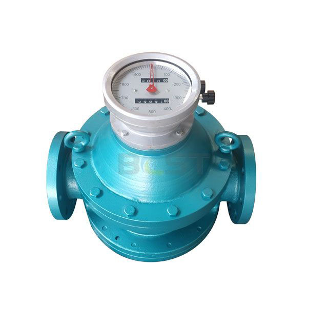
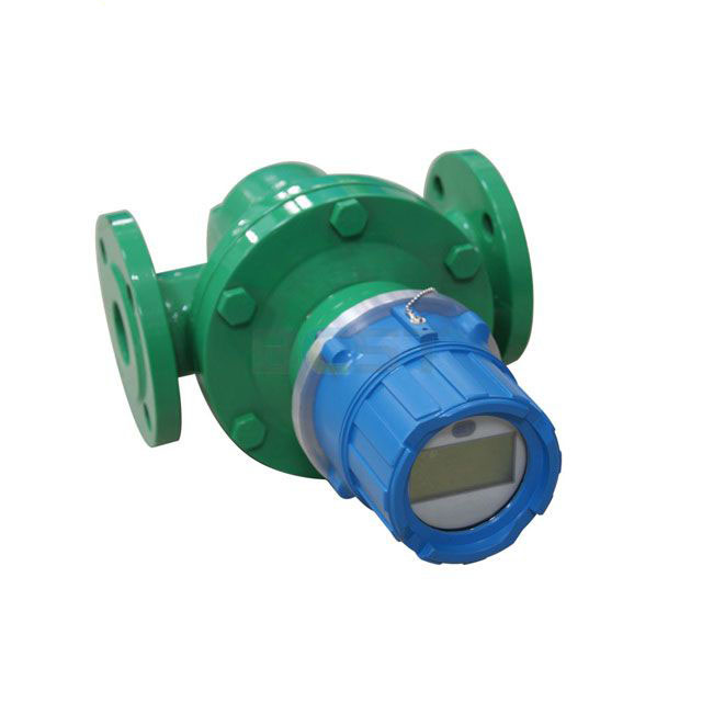
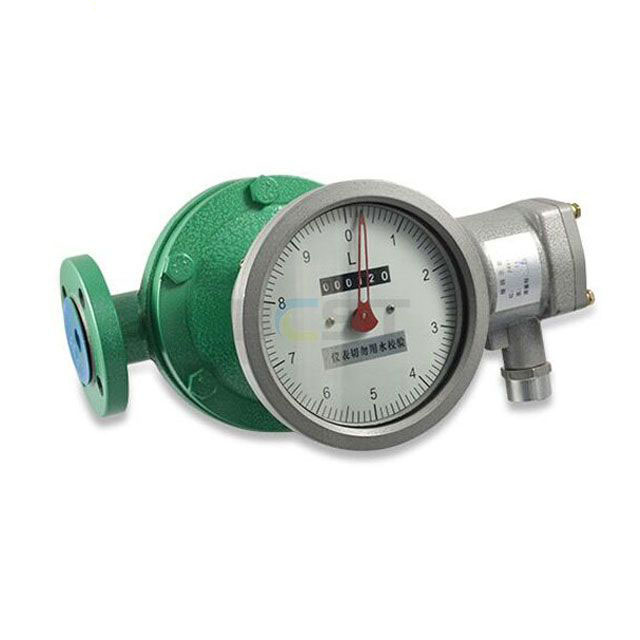
JC-LC oval gear meters are fitted with on-site pointer indication and roller integration device which can indicate the liquid flow and intermittent flow passing through the pipeline. For the different liquids (acid, alkali, salt, organic solution etc.), the meters can be made of different materials (cast iron, cast steel, stainless steel etc.). The meters are widely used for the flow measurement in the field of petroleum, chemical, chemical fiber, traffic, food industries and commerce, medical and sanitary departments.
Operation Principle
Oval gear meter is generally comprised of a flow transducer and a counter mechanism. The main part of the transducer is a measuring chamber which consists of a pair of oval wheels and a sealing coupling. The counter mechanism contains speed reduction gears, adjusting device, counter, and pulse transmitter etc.
In the measuring chamber, a pair of oval wheels and cover plate make a crescent shape cavity which is used as a measuring unit. The oval wheels are rotated by the pressure difference in the inlet and outlet of the meter and drive the inlet liquid through the cavity to the outlet, each revolution of the oval wheels displaces fluid four time the volume of the cavity, the total revolutions of the oval wheels and the revolution rate will be transferred to the mechanical counter, and the total liquid volume and instantaneous flow will be known by the pointer display and the roller integration. The attached signal generator converts the rotary axial angular shift to the pulse signal and then transmits it to the electrical indicator for remote integrated flow and instantaneous flow indication and control.
Tags: Oval Gear FlowmeterOval Gear Flow meterpositive displacement flow meterOval Gear Flow transmitterpositive displacement flow transmitterOval Gear Flowmetereoval gear oil flowmeteroval gear diesel flowmeterhigh viscosity Oval Gear Flow meterOval Gear flow meter with 4-20ma
Technical Parameter for JCLC Oval Gear Flowmeter
1. Materials of main parts and the nominal operating pressure
| Shell and cover | cover plate | oval wheel | Rotary shaft | Sheath of shaft | Nominal pressure(MPa) | |
| JCLC-A | Cast steel | Cast iron | Stainless steel | Bronze(with oil) or rolling bearing | 1.6 | |
| JCLC-E | Cast steel | Cast iron、Stainless steel | Under DN50 6.3
DN80-100 4.0 DN150-200 2.5 |
|||
| JCLC-Q | Cast iron | Cast iron | Alloy aluminum, engineering material | graphite | 1.6 | |
| JCLC-B、C | Stainless steel | Stainless steel | Stainless steel | graphite | 1.6、2.5 | |
| JCLC-L | Cast
aluminum |
Cast iron,
Stainless steel |
Alloy
aluminum, engineering material |
Bronze(with oil)、graphite、rolling bearing | 1.6 | |
| Notes:1. 0Cr18Ni12Mo2Ti for type JCLC-C; 0Cr18Ni9Ti for type JCLC-B
2. Flange is convex under 2.5MPa ,and roughness at 6.3 MPa;and both of the above at 4.0 MPa。 |
||||||
2. Accuracy class 0.5, class 0.2 (normal operating temperature -10℃~+60℃)
3. Measured media temp. (environment temperature -41℃~+50℃)
JCLC-A、B、C: -20℃~+60℃; 60℃~200℃(with high temp. radiator installed)
JCLC-Q、L: -20℃~+60℃;
4. Explosion-proof mark: ExiaⅡCT5, dⅡBT4
5. Flow range: unit: m3/h
| Type | DN | Viscosity (mPa. s) | ||||||||
| <0.3
<0. |
0.3~0.8
0. |
0.8~2 | 2~200 | 200~1000
|
1000~2000
|
|||||
| JCLC-10 | 10 | 0.2-0.5 | 0.08-0.5
4 |
0.08-0.5 | 0.05-0.5 | 0.06-0.3 | 0.03-0.3 | 0.03-0.2 | ||
| JCLC-15 | 15 | 0.75-1.
5 |
0.3-1.5 | 0.3-1.5 | 0.15-1.5 | 0.2-1.0 | 0.1-1.05 | 0.07-0.75 | ||
| JCLC-20 | 20 | 1.5-3 | 1-3 | 0.4-3 | 0.5-3 | 0.3-3 | 0.4-2.1 | 0.2-2.1 | 0.15-1.5 | |
| JCLC-25 | 25 | 4-6 | 3-6 | 2-6 | 0.8-6 | 1-6 | 0.6-6 | 0.8-4.2 | 0.4-4.2 | 0.3-3 |
| JCLC-40 | 40 | 9-15 | 7.5-15 | 5-15 | 2-15 | 2.5-15 | 1.5-15 | 2.1-10.5 | 1.0-10.5 | 0.7-7.5 |
| JCLC-50 | 50 | 10-24 | 8-24 | 8-24 | 3-24 | 4.8-24 | 2.4-24 | 2.4-16.8 | 1.6-16.8 | 1.2-12 |
| JCLC-B40、50 | 40、50 | 8-20 | 6-20 | 6-20 | 4-20 | 4-20 | 2-20 | 2.8-14 | 1.4-14 | 1.0-10 |
| JCLC-B65 | 65 | 27-40 | 20-40 | 15-40 | 5-40 | 8-40 | 4-40 | 5.6-28 | 2.8-28 | 2-20 |
| JCLC-80 | 80 | 40-60 | 30-60 | 20-60 | 8-60 | 12-60 | 6-60 | 8.4-42 | 4.2-42 | 3-30 |
| JCLC-100 | 100 | 67-100 | 50-100 | 34-100 | 13.-100 | 20-100 | 10-100 | 14-70 | 6-70 | 5-50 |
| JCLC-150 | 150 | 127-190 | 95-190 | 64-190 | 24-190 | 38-190 | 19-190 | 26.6-133 | 13.3-133 | 9.5-95 |
| JCLC-200 | 200 | 227-340 | 170-340 | 114-340 | 43-340 | 56-340 | 34-340 | 47.6-238 | 23.8-238 | 17-170 |
| Accuracy
class |
0.5 | 0.5 | 0.2 | 0.5 | 0.2 | 0.5 | 0.2 | 0.5 | 0.5 | |
| Note | 1.“gal/h” could be used for special orders.
2.Flow range of type JCLC-A80.2 is 1760gal/h~13200gal/h |
|||||||||
Note: If the temperature of the metered liquid is higher than 80℃. the maximum flow fate will be 90% of the primary flow and the minimum will be 120%.
Model Selection for JCLC Oval Gear Flowmeter
| Type | Special symbol | Special function | Material | DN | Special require–ment | Allowable pressure | Counter | Pulse transmi-tter | Accura-cy | Illumination | ||
| shell | rotor | |||||||||||
| 1 | 2 | 3 | 4 | 5 | 6 | 7 | 8 | 9 | 10 | 11 | 12 | |
| JCLC- | Oval flowmeter | |||||||||||
| U | Matchedthermal insulation sleeve | |||||||||||
| G | tube thread | |||||||||||
| H | Flowmeter of welded steel | |||||||||||
| D | Flowmeter of batch meter | |||||||||||
| N | Flowmeter of large viscosity | |||||||||||
| SP | flowmeter for foodstuff | |||||||||||
| T1、2 | High temp. with radiator (1for long,2 for short) | |||||||||||
| Q | Meter for gas | |||||||||||
| A | Cast iron meter | |||||||||||
| B/C ////B/C B/C B/C(C) | Stainless steel meter | |||||||||||
| E | Cast steel meter | |||||||||||
| L | Alloy aluminum meter | |||||||||||
| A | Material is cast iron | |||||||||||
| B/C | Material is stainless steel | |||||||||||
| L | Material is alloy aluminum | |||||||||||
| Z | Material is engineering material | |||||||||||
| 10 | Nominal diameter 10 mm | |||||||||||
| … | …… | |||||||||||
| 200 | Nominal diameter 200 mm | |||||||||||
| S(K) | Flange shrunk(widened) | |||||||||||
| Ⅱ | Improved type | |||||||||||
| Note:
1 When the oval wheel’s material is same with the shell’s, it can be not indicated; |
.2/ | 1.6 MPa | ||||||||||
| .3/ | 2.5 MPa | |||||||||||
| .4/ | 1.0 | 4.0MPa
2.0 |
||||||||||
| .6/ | 6.3 MPa | |||||||||||
| 2.’ B’-OCr18Ni9Ti;C-OCr18Ni12Mo2Ti;
3.B before generator means separation generator; 4.if without radiator the meter could be only marked T; |
A、A1 | Used for counter under DN40 | ||||||||||
| A5、J1 | Used for counter above DN50 | |||||||||||
| ELZ | Counter with electric indicator | |||||||||||
| A6、 Z | return-to-zero counter | |||||||||||
| 5. At past JCLC11 was used as on-site indicator and JCLC12 as meter with transmitter. New clients are proposed to use this new marker and old customers may use the old ones. | FX | used for type LC13 | ||||||||||
| 12Vthree-cable pho-electri transmitter | ||||||||||||
| GF-Ⅱ | 24V three-cable pho-electri transmitter | |||||||||||
| QF-Ⅰ | 12V two-cable inductance transmitter | |||||||||||
| QF-Ⅱ | 12V three-cable inductance transmitter | |||||||||||
| QF-Ⅲ | 24V three-cable inductance transmitter | |||||||||||
| MF-123 | 器 | 4—20mAanalog signal output | ||||||||||
| J | High accuracy meter | |||||||||||
How to order for JCLC Oval Gear Flowmeter
- Medium
- Pipe size
- Working pressure
- Working temperature
- Process connection
- Medium viscosity
- Flange standard
JCLC Oval Gear Flowmeter

