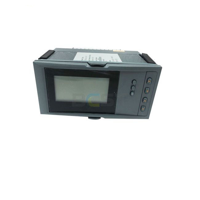
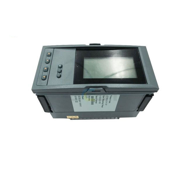
JCPR7600 LCD Flow (Heat) Totalizer / Recorder
JCPR7600 LCD Flow Totalizer is mainly designed for trading discipline in regional central heating, and calculating steam, and high precision flow measurement.
- Price Term: FOB/CIF/EXW/DAP
- Package: Exported Wooden case or according to customer request
- Delivery Time: 7 to 10 working days
- Transports: By sea, by air, by high express
- Shipment Port: Shanghai Port
- Origin of Place: Jiangsu
- Warranty: 12 Months
- Introduction
- Parameters
- Model
- Dimension
- Installation
JCPR7600 LCD Flow (Heat) Totalizer / Recorder
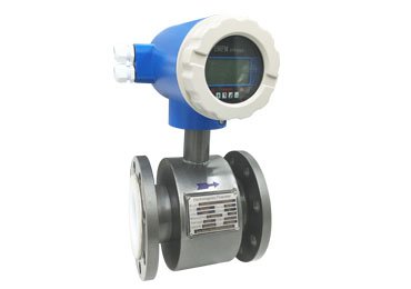
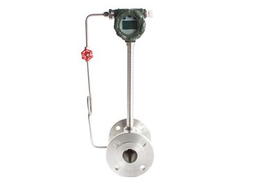
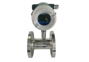
JC-7600 LCD flow totalizer is mainly designed for trading discipline between supplier and customer in regional central heating, calculating steam, and high precision flow measurement. It’s a fully functional secondary instrument based on a 32-bit ARM microprocessor, high-speed AD, and large-capacity storage. The instrument has fully adopted surface-mount technology. It has good EMC ability and high reliability because of heavy protection and isolation in design. It is embedded in RTOS, USB Host, and high-density FLASH memory, recording 720-day length sampling data. It can automatically identify saturated steam and superheated steam. It can also be used for process monitoring and volume control of steam heat. History data recorded in the instrument can be copied to a USB disk at any time and analyzed by DTM software on a PC. The instrument may be used together with various flow sensors such as Orifice Plate, V-cone, vortex, etc. Besides, it also features good performance in anti-theft and power failure protection.
Technical Parameter for JCPR7600 LCD Flow (Heat) Totalizer / Recorder
| Measurement input | ||
| Input signal | Current: 0-20mA, 0-10mA, 4-20mA, √0-10mA, √4-20mA
Input impedance: ≤100Ω Maximum limit of input current: ≤ 30mA |
|
| Voltage: 0-5V, 1-5V, 0-10V (customized), √0-5V, √1-5V, 0-20mV, 0-100mV
Input impedance: ≥ 500KΩ |
||
| Thermal resistance: Pt100, Cu50, Cu53, Cu100, BA1, BA2 | ||
| Linear resistance: 0-400Ω | ||
| Thermocouple: B, S, K, E, T, J, R, N, F2, Wre3-25, Wre5-26 | ||
| Frequency signal: range: 0-10KHz; wave shape: rectangular, sine wave, square wave | ||
| Output | ||
| Output signal | Analog output: 4-20mA (load resistance ≤ 480Ω), 0-20mA (load resistance ≤ 480Ω)
0-10mA (load resistance ≤ 960Ω), 1-5V (load resistance ≥ 250KΩ) 0-5V (load resistance ≥ 250KΩ), 0-10V (load resistance ≥ 4KΩ) (customized) |
|
| Alarm output: relay control output: AC220V/2A, DC24V/2A (resistive load) | ||
| Feed output: DC24V±1, load current ≤ 50mA | ||
| Communication output: RS485/RS232, 1200-9600bps, Protocol: MODBUS RTU. Communication distance: 1Km for RS-485 and 15m for RS-232. | ||
| Comprehensive parameters | ||
| Measurement precision | 0.2%FS±1d | |
| Setting mode | Light touch control panel for setting parameter, which will be stored permanently even in case of power failure, and can be locked & protected with a password. | |
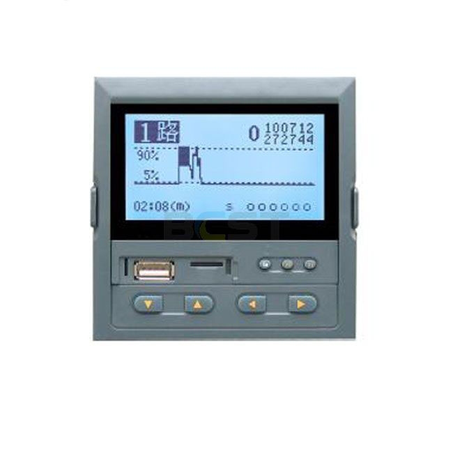
| Display mode | 3.5” matrix 128*64 LCD screen with backlight (black characters on a white screen).
Display pages include Digits, Curves, Bar graphs, and so on. Pages switch conveniently on the panel. History data can be searched, and the time scale of curves is changed by operating proper keys on the panel. |
|
| Record interval | 9 options for your choice: 1s, 2s, 4s, 6s, 15s, the 30s, 60s, 120s, and 240s | |
| Storage time | 3 days (record interval of 1s) – 720 days (record interval of 240s) | |
| Printer interface: RS-232C; Serial-interface printer: SP-A40SH | ||
| Operating environment | Ambient temperature: 0-50℃; relative humidity: ≤ 85RH; isolated from strongly corrosive gas | |
| Power supply | AC 100-240V (switch power), 50/60HZ; DC 20-29V (switch power) | |
| Power consumption | ≤ 5W | |
| Structure | – Standard panel-mounted instrument structure | |
Model Selection for JCPR7600 LCD Flow (Heat) Totalizer / Recorder
| ①Compensation input mode | ③Alarm output (Note 1) | ||
| Code | Compensation input mode | Code | Alarm channel (Relay contact output) |
| 01
02 |
Single-channel uncompensated input
Temperature/pressure compensated input |
X
1 2 3 4 5 6 |
No output
1 alarm relay 2 alarm relay 3 alarm relay 4 alarm relay 5 alarm relay 6 alarm relay |
| ②Specification | |||
| Code | Width*height*depth | ||
| A
B C |
160*80*110mm (horizontal)
80*160*110mm (vertical) 96*96*110mm (square) |
||
| ④Power supply | |||
| Code | Voltage range | ||
| A
D |
AC/DC 100~240V (50/60Hz)
DC20~29V |
||
| ⑤Auxiliary functions (all functions below may be selected separated with “/”; those not required may be omitted) | |||
| Transmission output (Note 1) | Communication output | ||
| Code | Output channel | Code | Communication interface |
| 1
2 3 4 |
1 transmission output
2 transmission outputs 3 transmission outputs 4 transmission outputs |
D1
D2 D3 |
RS-485 interface (Modbus RTU)
RS232 interface (Modbus RTU) RS232C printer interface |
| Feed output | |||
| Code | Feed output (output voltage) | ||
| 1P
2P |
1 feed output
2 feed outputs For example, “2P (12/24) means 2 feed outputs with 12V and 24V feed output respectively. |
||
| Applicable to instruments with recording function | |||
| USB data transfer | Expansion function | ||
| Code | Data transfer | Code | Expansion function |
| U | USB disk (1GB USB flash disk) | SD | SD card expansion (8GB) |
Note: 1. Transmission output and alarm output may be combined, provided that transmission output + alarm output ≤ 6. If the flow signal type is Frequency, the maximum transmission output is 2, and transmission output + alarm output ≤ 4
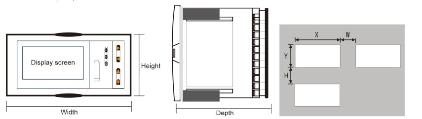
Dimension
| Dimension | Hole Size | Minimum Distance Between Instruments | |||||
| Type | Width | Height | Depth | X | Y | W | H |
| A | 160 | 80 | 110 | 152+0.5 | 76+0.5 | 38 | 34 |
| B | 80 | 160 | 110 | 76+0.5 | 152+0.5 | 34 | 38 |
| C | 96 | 96 | 110 | 92+0.5 | 92+0.5 | 38 | 38 |
(1) Installing the instrument on the mounting panel
Drill installation holes of proper size according to the instrument requirements and put the seal ring on the instrument’s back. Then insert the instrument right to the installation hole and install the attaching clamps to the back of the board to fix the top and bottom surface of the instrument and push two clamps forward so that the instrument could be fixed on the board. Finally, take the protective film off the screen. (If multiple instruments would be installed on one board, the minimum distance between instruments as specified in the table above shall be considered to ensure adequate heat dissipation and space for installation.)
(2) How to take the core out of the enclosure
The core of the instrument may be taken out of the enclosure. Push aside two buckles on each side of the front panel, and pull the front panel outward to separate the core and enclosure. When reassembly, insert core into the enclosure tightly and fasten them with buckles for reliability.
(3) Installation instructions
★ Cable selection, instrument installation, and electrical wiring must comply with VD0100 “Relevant Rules on Circuit Installation under 1,000V” or relevant local rules;
★ Professionals must complete electrical wiring;
★ Fuse shall be used in load circuit to protect the circuit and ensure that the relay contact will be open in the case of short circuit or load exceeding the maximum capacity of relay;
★ Separate wiring shall be made for input, output, and power supply, respectively and parallelism shall be avoided;
★ No other load shall be connected to the power terminal of the instrument;
★ Shielded twisted wires shall be used for sensors and communication.
(4) Standard wiring instructions
★ DC signal input (process input)
- To reduce electrical interference, wires carrying low-voltage DC signals and sensors input shall be far away from high-voltage-bearing wires. If not, shielded wires shall be used and grounded at the same point;
- Any device connected between sensors and terminals may influence measurement accuracy due to resistance or current leakage.
★ Thermocouple or pyrometer input
Compensating lead wires appropriate to the thermocouple shall be used as extension wires, which must be shielded.
★ RTD (thermal resistance) input
The resistance of the three wires must be the same and shall not exceed 15Ω each.