With the rapid growth of the global population and rapid industrial development, the global water resources situation is rapidly deteriorating. As a result, the “water crisis” is becoming increasingly severe. In response to this situation, the London government will invest 300 billion yuan in the “Eleventh Five-Year Plan” period to build and reconstruct thousands of new sewage treatment plants to promote urban sewage treatment and use, pollution reduction.
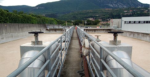
In the sewage treatment process, the flow of raw sewage is a crucial parameter to be tested. Because the original sewage contains particles, suspended matter, solid-liquid mixture, corrosive media, and electromagnetic flowmeter features can measure the flow of acid, alkali, salt solutions,and solid particles were containing (such as slurry), or fiber liquid. Therefore, the sewage treatment plant used two electromagnetic flowmeters for the flow measurement of the original sewage.
I.The Working Principle of Electromagnetic Flowmeters
The basic principle of the electromagnetic flowmeter is Faraday’s law of electromagnetic induction, which states that when a conductor cuts through magnetic motion in a magnetic field, it generates an induced electric potential at both ends.
When measuring flow, a conductive liquid, equivalent to a conductive metal bar in Faraday’s test, flows through a magnetic field perpendicular to the flow direction at an average velocity v. The flow of the conductive liquid induces a voltage on the measuring electrode proportional to the average flow velocity. The induced voltage signal E is detected by a pair or more electrodes in direct contact with the liquid.
II.Electromagnetic Flowmeter Features
2.1 No resistance elements in the measuring pipeline, no additional pressure losses, not easy to clog, significant energy savings;
2.2 Long sensor life due to no moving parts in the measuring channel and minor wear and tear;
2.3 The short straight section of pipe required for the sensor makes it easy to install;
2.4 Properly selected electrode and lining materials for corrosion and wear resistance;
2.5 Bi-directional measuring system for forward and reverse flow;
2.6 Flow is measured as a volumetric flow rate, unaffected by changes in density, viscosity, temperature, pressure, and conductivity of the flow;
2.7 Linear relationship between sensor induced voltage signal and average flow rate, high measurement accuracy (±0.3 to -0.5%), wide range ratio (1:150).
III.Electromagnetic Flowmeter Selection
Instrument selection is essential. The relevant information shows that about 2/3 of the instrument failure is due to wrong selection or improper use in the actual application.
Therefore, determining the choice of electromagnetic flowmeter should also be based on different processes, environment, measurement, media,, and other comprehensive considerations.
3.1 Size Selection
According to the process pipe diameter, pipe pressure,and sewage flow rate provided by the wastewater treatment plant, the electromagnetic flowmeter manufacturer would assit to select the suitable size based on the flow rate and pipeline .
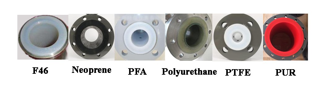
3.2 Lining, Electrode material selection
Electromagnetic flowmeter is mainly used to measure the conductivity ≥ 5μS/cm fluid flow, should be based on the measured material corrosion, abrasion, temperature and condensation characteristics and price affordability, should choose different lining, electrode materials.
Electromagnetic flowmeter lining materials are medium corrosion resistance, resistance to general low concentration of acid, alkali, salt neoprene material, strong resistance to abrasion and available corrosion resistance polyurethane rubber, strong corrosion resistance and suitable for high-temperature PTFE, chemical properties equivalent to PTFE tensile, pressure-resistant polyethylene per fluoride, resistant to dilute acids, alkalis, salt temperature <60 ℃ polyethylene and temperature <100 ℃ polyphenylene sulfide, etc.
The electrode material is installed in the inner wall of its pipe. It is in direct contact with the measured material, so it should be selected according to the corrosiveness of the rhythmic material. For example, Titanium electrode is suitable for the erosion of sea water, all kinds of chloride and hypochlorite, oxidized acids (including Fuming sulfuric acid), organic acid, alkali; it is not resisting the erosion of purer reducing acids( such as sulfuric acid, hydrochloric acid); if oxidizer exists in acids (such as nitric acid, Fe+++. Cu++) the erosion for Titanium will reduce greatly.
The neoprene lining and stainless steel 316L electrodes were chosen according to the primary treatment of domestic and industrial wastewater at the plant and the price acceptable to the user.
3.3 Selection of the Level of Protection
According to national standards, the sensors are available in IP65 water spray type and IP68 submersible type with two protection levels. According to the actual installation location of the user in a low shaft, so the sensors choose the IP68 dustproof submersible type.
- Choice of additional features
(A)For the selected basic type, electromagnetic flowmeter has been with LCD, 4 ~ 20mA current output and 0 ~ 1 KHz frequency output, according to the flowmeter and computer communication requirements, need to increase the RS-485 communication port function.
(B)For sensor installation below ground level, a remote type should be selected.
IV. Installation and Commissioning of Electromagnetic Flowmeters
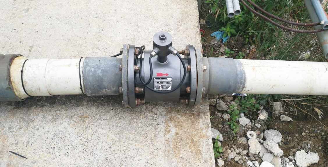
4.1 Installation Instructions
(A)The installation point is selected at the pipe after confirming the flow direction of the measured substance. The installation point is selected in such a way that the measuring tube is filled with liquid at all times to prevent errors caused by the indication not being at the zero position due to the absence of liquid in the measuring tube.
(B)Straight pipe section guaranteed in the first 5D and then 3D
To obtain an instrument gauge, the length of the straight pipe section on the upstream side of the sensor should be no less than 5D and no less than 3D on the downstream side (D is the nominal diameter of the sensor). If there are more than two elbows or other flow blockers on the upstream side of the sensor, the front straight section should be greater than 10D.
(C)Signal electrode in the horizontal direction
When mounted horizontally, the electrode axis should be parallel to the horizon, as the electrode at the bottom is susceptible to being covered by sediment and occasional air bubbles in the measured medium brushing over the surface of the electrode, causing fluctuations in the output signal.
(D)Avoid vibration sources, magnetic sources (high power motors, transformers) as far as possible
Due to the electromagnetic flowmeter measurement induction voltage is very small, low voltage, vulnerable to the influence of external electromagnetic noise, it should be installed in a reliable grounding connection (across)
4.2 Converter Installation and Commissioning
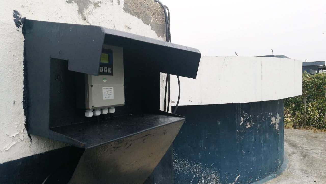
Integrated electromagnetic flowmeter without separate converter installation, split converter installed near the sensor or instrument room, there is a large choice of places, good environmental conditions. The distance between the converter and the sensor is subject to the measured medium conductivity and signal cable type, the cable distribution capacitance, wire cross-section,, and shielding layer number, with the manufacturer instrument attached (or the specified model) of the signal cable. When the conductivity is low, the transmission distance is long. A two-layer shielded cable should be used.
V. Instrument Commissioning and Troubleshooting
Before installation , the pipeline and flowmeter should be thoroughly inspected, including pipeline debris and other cleanup electrodes at the dry treatment. It also includes the inspection of the electrical circuit. The grounding of the line should be tested to ensure reliable grounding, insulation resistance,and grounding resistance tests are also required.